
Sub Panel Sizing: Feeder Wire, Breaker, Neutral, and Ground
- 05 Aug, 2026
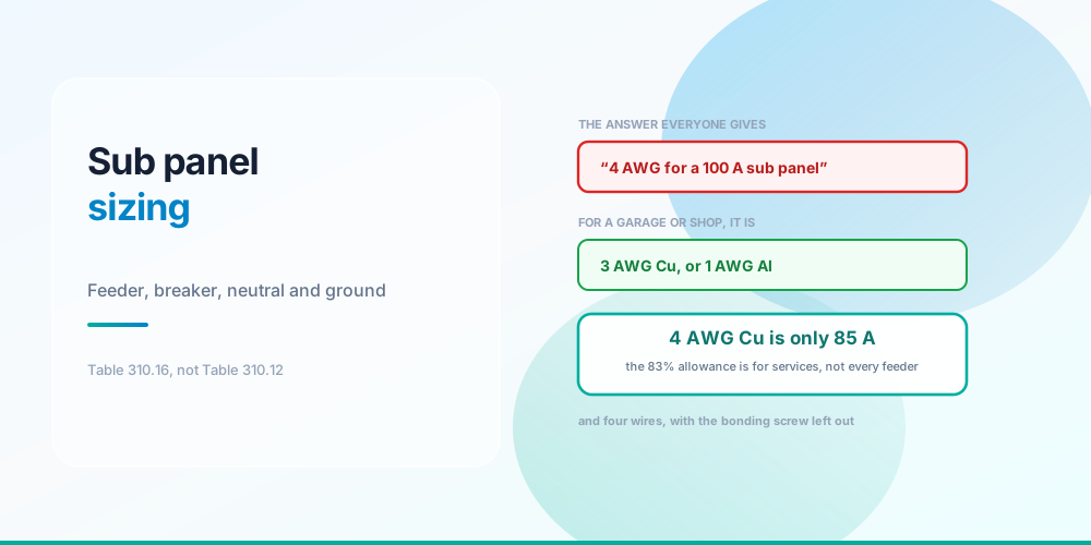
Search “what size wire for a 100 amp sub panel” and nearly every result says 4 AWG copper.
For an ordinary garage or shop subpanel, that is wrong. It needs 3 AWG copper, or 1 AWG aluminium.
The reason is a distinction the popular answer skips: the reduced conductor sizes in Table 310.12 apply to a dwelling service, or to the single feeder carrying an entire dwelling load. A subpanel serving part of a house is neither, so it goes to Table 310.16 - where 4 AWG copper is only rated 85 A, fifteen amps short.
Who Actually Gets the 83% Allowance
The 83% allowance is narrower than everyone thinks
Table 310.12 exists because a dwelling’s service has enormous diversity behind it - the calculated load already assumes not everything runs at once, and decades of field experience show service conductors sized at 83% of the rating never get warm. So the table lets a 200 A dwelling service run on 2/0 copper instead of 3/0.
Read its scope carefully, though. It covers:
- Dwelling service conductors - utility to main disconnect.
- A feeder carrying the entire dwelling load - for instance a meter-main outside feeding the one panel that serves the whole house.
It does not cover a garage subpanel, a shop subpanel, a subpanel in a detached building, or any feeder in a non-dwelling. Those carry part of the load, and part of a load has less diversity behind it, not more.
The confusion is understandable, because the two situations look identical from the panel end. The test is not what the conductor connects to - it is whether that conductor carries the whole dwelling load.
The Two Tables, Side by Side
One rating, two answers - pick the right table
| Feeder | Ordinary subpanel (310.16) | Whole-dwelling feeder (310.12) | EGC Cu | EGC Al |
|---|---|---|---|---|
| 60 A | 6 Cu / 4 Al | n/a | 10 | 8 |
| 100 A | 3 Cu / 1 Al | 4 Cu / 2 Al | 8 | 6 |
| 125 A | 1 Cu / 2/0 Al | 2 Cu / 1/0 Al | 6 | 4 |
| 150 A | 1/0 Cu / 3/0 Al | 1 Cu / 2/0 Al | 6 | 4 |
| 175 A | 2/0 Cu / 4/0 Al | 1/0 Cu / 3/0 Al | 6 | 4 |
| 200 A | 3/0 Cu / 250 kcmil Al | 2/0 Cu / 4/0 Al | 6 | 4 |
One full conductor size apart at every rating. Note that Table 310.12 has no 60 A row - 230.79(C) makes 100 A the minimum for a one-family dwelling service, so the table simply starts there.
The ampacities behind the 100 A case, from the 75°C column:
4 AWG Cu  =  85 A   ← the popular answer, 15 A short
3 AWG Cu  = 100 A   ← what an ordinary 100 A subpanel needs
2 AWG Al  =  90 A   ← 10 A short
1 AWG Al  = 100 A   ← what it needs in aluminium
Why 75°C? Because 110.14(C) limits you to the temperature rating of the terminations, and equipment terminations for circuits above 100 A - and virtually all breakers and lugs regardless - are rated 75°C. The 90°C column exists as a derating base only, never as a starting ampacity. That distinction is worked through in Wire Derating Explained.
If the run is long, voltage drop may govern
A detached garage 120 feet from the house is common, and at that distance drop frequently demands a larger conductor than ampacity does. The 3% figure is not enforceable - it lives in informational notes to 215.2(A) - but design to it anyway. Voltage Drop Calculation covers what the code actually says.
The Other Half: Four Wires and No Bonding Screw
Four wires, and the bonding screw stays out
Conductor size is the part people research. This is the part that fails inspection.
A subpanel needs a four-wire feeder: two hots, a neutral, and an equipment grounding conductor. Inside the subpanel:
- The neutral bar is isolated from the enclosure. Remove the green bonding screw, or don’t install it.
- The ground bar is bonded to the enclosure. Most subpanels need one added.
- The two bars are not connected to each other.
Neutral and ground are joined exactly once in the whole system, at the service disconnect, by the main bonding jumper - 250.24(A)(5). Bond them a second time at the subpanel and normal return current now has two paths home: the neutral, and the equipment grounding conductor.
That means normal load current flowing on the grounding conductors, the conduit, the enclosures, and any metal bonded to them. It works perfectly. Nothing trips. And it is genuinely dangerous, because the grounding system is now energised in normal operation rather than only during a fault. 408.40 is the section that requires the separation in a subpanel.
The old three-wire feeder, with the neutral doing double duty, was permitted for detached buildings under earlier codes. That allowance is gone. Four wires, always.
Detached buildings need their own electrode
250.32 requires a grounding electrode system at the detached structure - typically a ground rod, or two spaced at least 6 ft apart where a single rod does not achieve 25 ohms. This is in addition to the equipment grounding conductor in the feeder, not instead of it. A rod on its own is not a fault-clearing path: 120 V through a 25-ohm rod is 4.8 A, which will never trip a 20 A breaker. The EGC clears faults; the rod handles lightning and voltage stabilisation. See Grounding vs Bonding.
A detached building also needs a disconnecting means under 225.31, and if there is a receptacle in that garage or shop, 210.8 GFCI requirements apply.
Sizing the Feeder Breaker
The breaker in the main panel protects the feeder conductor, so it is sized to the conductor rather than to the subpanel’s rating. In practice you work the other way: decide the subpanel rating, size the conductor to carry it, and fit a breaker matching the conductor’s ampacity.
A subpanel rated 100 A does not have to be fed at 100 A. Fitting a 100 A panel on a 60 A feeder is completely legal and often sensible - you get the spaces without the conductor cost. The panel’s rating is a maximum, not a requirement.
What you cannot do is exceed the feeder’s ampacity, and - separately - the sum of the subpanel’s breakers is allowed to exceed the feeder rating. That surprises people, but it is the same diversity principle as everywhere else: a 60 A feeder can supply a subpanel with 200 A of breakers in it, because they will not all draw simultaneously. What matters is the calculated load, not the sum of the ratings.
Common Mistakes
- Using 4 AWG Cu for an ordinary 100 A subpanel. It is 85 A. The 83% allowance does not reach here.
- Applying Table 310.12 to any feeder. It covers a dwelling service or a whole-dwelling feeder only.
- Leaving the bonding screw in the subpanel. Puts normal current on the grounding conductors.
- Running a three-wire feeder. No longer permitted, even to a detached building.
- Sharing one bar for neutrals and grounds. 408.40 requires the neutral bar isolated.
- Omitting the detached building’s grounding electrode. 250.32 requires it as well as the EGC.
- Relying on a ground rod to clear faults. 4.8 A through 25 ohms trips nothing. That is the EGC’s job.
- Starting from the 90°C column. 110.14(C) caps you at the termination rating, which is 75°C.
- Assuming breakers must sum to the feeder rating. They may exceed it; the calculated load governs.
- Ignoring voltage drop on a long run to a garage. At 120 ft, drop often governs over ampacity.
Size the Feeder
Service & Feeder Wire Size Calculator - enter the feeder rating and material and it returns the conductor from the correct table, with the neutral and equipment grounding conductor to match. It distinguishes a dwelling service or whole-dwelling feeder, which gets the Table 310.12 allowance, from an ordinary subpanel feeder, which does not.
Check the run length with the Voltage Drop Calculator, the ground with the Ground Wire Size Calculator, and whether you even need the subpanel with the Panel Spaces & Tandem Breaker Calculator - that question is covered in Panel Is Full.
Sources & standards: NEC (NFPA 70) 2023 - Table 310.16 for general conductor ampacity, Table 310.12 for dwelling services and feeders carrying an entire dwelling load (the 83% allowance, whose scope is set by the table’s own title), 110.14(C) for termination temperature limits, Table 250.122 for equipment grounding conductors, 250.24(A)(5) for the main bonding jumper at the service, 408.40 for isolating the neutral bar in a panelboard other than at the service, 250.32 for grounding electrodes at separate structures, 225.31 for the disconnecting means at a detached building, 230.79(C) for the 100 A minimum one-family dwelling service, and 210.8 for GFCI. The 3% voltage drop figure appears in an informational note to 215.2(A) and is not an enforceable requirement, though it is strong practice and many specifications adopt it. Local amendments override the model code and the AHJ has final say. Have subpanel work performed by a licensed electrician under permit.
FAQ
What size wire do I need for a 100 amp sub panel?
For an ordinary subpanel - a garage, a shop, an addition - 3 AWG copper or 1 AWG aluminium, from Table 310.16 at 75°C. The widely repeated answer of 4 AWG copper comes from Table 310.12, whose 83% allowance applies only to a dwelling service or a feeder carrying an entire dwelling load. 4 AWG copper is rated 85 A, which is fifteen amps short of 100.
When does the Table 310.12 83% allowance apply?
To dwelling service conductors, and to the single feeder carrying an entire dwelling load - for example a meter-main outside feeding the one panel that serves the whole house. It does not apply to a subpanel serving part of a house, a detached building’s subpanel, or any non-dwelling feeder. The test is whether that conductor carries the whole dwelling load, not what it connects to.
Does a sub panel need a four-wire feeder?
Yes, always. Two hots, a neutral, and a separate equipment grounding conductor. The older three-wire arrangement, where the neutral doubled as the grounding path to a detached building, was permitted under earlier codes and no longer is. Inside the subpanel the neutral bar must be isolated from the enclosure and the ground bar bonded to it, per 408.40.
Why can’t neutral and ground be bonded in a sub panel?
Because they are joined exactly once in the system, at the service disconnect, by the main bonding jumper under 250.24(A)(5). Bond them again downstream and normal return current gains a second path home - through the equipment grounding conductor, the conduit and every metal enclosure bonded to it. Everything appears to work and nothing trips, but the grounding system is now carrying current in normal operation.
Does a detached garage sub panel need its own ground rod?
Yes. NEC 250.32 requires a grounding electrode system at a separate structure, typically a rod or two rods spaced at least 6 ft apart. It is in addition to the equipment grounding conductor in the feeder, not a substitute for it. A rod cannot clear faults - 120 V through a 25-ohm rod is only 4.8 A, which will never trip a breaker. The EGC clears faults; the rod handles lightning and voltage stabilisation.
Can the breakers in a sub panel add up to more than the feeder?
Yes, and this is normal. The feeder is sized to the calculated load, not to the sum of the breaker ratings, because the circuits will not all draw simultaneously. A 60 A feeder can legitimately supply a subpanel containing 200 A of breakers. What matters is that the calculated load stays within the feeder’s ampacity and that the feeder breaker protects the conductor.
Does a 100 amp sub panel have to be fed at 100 amps?
No. A panel’s rating is a maximum, not a requirement. Fitting a 100 A panel on a 60 A feeder is entirely legal and often sensible - you get the breaker spaces without paying for the larger conductor. Just size the feeder breaker to protect the feeder conductor, and make sure the calculated load of everything on the subpanel stays inside what the feeder can carry.
What size ground wire does a sub panel feeder need?
From Table 250.122, keyed to the rating of the overcurrent device protecting the feeder - not to the conductor size. A 100 A feeder takes 8 AWG copper or 6 AWG aluminium; a 200 A feeder takes 6 AWG copper or 4 AWG aluminium. Note that where the phase conductors are upsized for voltage drop, 250.122(B) requires the equipment grounding conductor to be increased proportionally.