
Ohm's Law Explained: V, I, R, and the Power Wheel
- 04 Aug, 2026
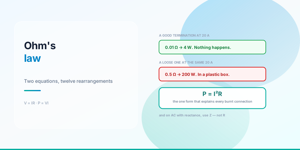
The power wheel with its twelve formulas is a poster, not a concept. There are two equations:
V = I × R
P = V × I
Everything else on the wheel is one of those two with a substitution made. Learn the two and you can derive the other ten in your head, which is more reliable than remembering which segment of a circle you’re supposed to cover with your thumb.
And one of the twelve does far more work in the field than the rest. P = I²R is why a loose connection burns, why a long run gets warm, and why doubling current quadruples the problem.
Twelve Forms, One Answer
Twelve formulas, two equations, one answer
On a 120 V circuit with 10 Ω of resistance:
| Solve for | Forms | Result |
|---|---|---|
| Volts | V = IR · V = P÷I · V = √(PR) | 120 V |
| Amps | I = V÷R · I = P÷V · I = √(P÷R) | 12 A |
| Ohms | R = V÷I · R = V²÷P · R = P÷I² | 10 Ω |
| Watts | P = VI · P = I²R · P = V²÷R | 1,440 W |
Which form you reach for depends on what you can measure. In the field you usually know volts and amps (a meter gives you both) so P = VI is the default. When you know amps and resistance - a conductor of known size and length - P = I²R is the one.
The Form That Explains Burnt Connections
P = I²R, in the space of a wire nut
| Joint | 5 A | 10 A | 15 A | 20 A |
|---|---|---|---|---|
| Tight, 0.01 Ω | 0.3 W | 1.0 W | 2.3 W | 4 W |
| Slack, 0.1 Ω | 2.5 W | 10 W | 22.5 W | 40 W |
| Loose, 0.5 Ω | 12.5 W | 50 W | 112.5 W | 200 W |
| Failing, 1.0 Ω | 25 W | 100 W | 225 W | 400 W |
Two hundred watts inside a wire nut. That’s a soldering iron, in a plastic box, behind drywall, with no ventilation. A joint that has gone from 0.01 Ω to 0.5 Ω - which is what a relaxed backstab or an under-torqued screw does - is dissipating fifty times what it did when it was tight, in the same physical space.
The squared term is what makes this vicious. Going from 10 A to 20 A on the same bad joint takes it from 50 W to 200 W. And heat increases resistance, which increases heat.
Worth comparing against the conductor itself. 12 AWG copper is 1.93 Ω per 1,000 ft, so a 100-foot run carries about 0.386 Ω of two-way resistance. At 15 A that’s 87 W of heat - a similar number to the bad joint, but spread over 200 feet of wire rather than concentrated at one screw. Same watts, completely different consequence. Power density is the thing that matters, not power.
This is exactly what an AFCI is listening for, and it’s the reason 110.14(D) requires terminations to be torqued to the manufacturer’s specification with a calibrated tool. Diagnosis is in AFCI and GFCI Nuisance Tripping.
Voltage Drop Is Just Ohm’s Law
The most common professional use of V = IR is voltage drop, where the “resistor” is the conductor:
VD = I × R_conductor (× 2 for single-phase, out and back)12 AWG at 15 A over 100 feet: 15 × 0.386 = 5.79 V, which is 4.8% of 120 V - past the conventional 3% design target.
The circular-mils shortcut you’ll see everywhere is the same equation with resistance expressed through a constant:
VD = (2 × K × I × L) ÷ cmil K = 12.9 copper, 21.2 aluminumK is just resistivity in ohm-circular-mils per foot, so this is V = IR wearing a hat. The full treatment, including the fact that the 3% figure lives in informational notes to 210.19(A) and 215.2(A) and is not enforceable code, is in Voltage Drop.
Where the DC Form Stops Working
On AC, the R in V = IR becomes Z
| Size | R (Ω/kft) | X (Ω/kft) | X ÷ R | Effective Z |
|---|---|---|---|---|
| 12 AWG | 1.9300 | 0.0680 | 0.04 | 1.6763 |
| 6 AWG | 0.4910 | 0.0640 | 0.13 | 0.4511 |
| 1/0 AWG | 0.1220 | 0.0550 | 0.45 | 0.1327 |
| 500 kcmil | 0.0258 | 0.0480 | 1.86 | 0.0472 |
On AC, a conductor has inductive reactance as well as resistance, and the quantity in V = IR becomes impedance. On small conductors reactance is negligible - 12 AWG’s X is 4% of its R, so treating it as a pure resistor is fine. By 500 kcmil the reactance is nearly twice the resistance, and ignoring it understates the drop badly.
Two things about that table are worth pausing on.
The formula is Z = R·cos θ + X·sin θ, not √(R² + X²). The magnitude form is only correct for a bolted fault where you want the total impedance; for voltage drop along a line you want the component in phase with the current. Getting this wrong is common and it is the subject of the Conductor Resistance Calculator.
On small conductors a lagging power factor slightly reduces line drop. Look at 12 AWG: its effective Z at PF 0.85 is 1.676, below its R of 1.93. That’s because R·cos θ shrinks faster than X·sin θ grows when X is tiny. On large conductors the opposite holds - 500 kcmil’s Z of 0.0472 is well above its R of 0.0258. The crossover sits near 1/0. This surprises people and it’s a genuine consequence of the arithmetic.
And that’s the doorway to power factor generally: once current and voltage are out of phase, volts × amps stops equalling watts. See kVA vs kW and Three-Phase Power. If the reason reactance exists on AC and not on DC isn’t obvious yet, AC vs DC starts from the waveform.
One more thing decides which quantity is shared before any of this arithmetic applies: whether the components sit in one current path or several. Series vs Parallel Circuits covers that, including the fact that a loose termination is simply an unwanted resistance in series with the load.
Practical Uses
Sizing a conductor by heat rather than by table. Ampacity tables already encode I²R against an assumed thermal environment, which is why derating exists at all - see Wire Derating Explained.
Finding a bad connection by voltage. Measure the voltage across a suspect joint while it carries load. Any measurable drop across a connection that should be a few milliohms tells you it isn’t. This is a better test than resistance-checking a de-energised joint, because a bad connection often reads fine cold.
Checking a heating element. A 4,500 W water heater element on 240 V should read 240² ÷ 4,500 = 12.8 Ω. Open circuit means a failed element; substantially low means a partial short.
Estimating load from resistance. Anything purely resistive - heaters, incandescent lamps, elements - follows P = V²÷R exactly. Motors and electronics don’t, because they’re not resistive.
Common Mistakes
- Memorising the wheel instead of the two equations. V = IR and P = VI generate the rest.
- Using R instead of Z on AC. Fine at 12 AWG, badly wrong at 500 kcmil.
- Using √(R² + X²) for voltage drop. That’s the fault-current form. Line drop wants R·cos θ + X·sin θ.
- Forgetting the factor of 2 on single-phase drop. Current goes out and comes back.
- Applying P = V²÷R to a motor. Motors aren’t resistive; use nameplate data and power factor.
- Ignoring the squared term. Doubling current quadruples heat, in a conductor and in a joint.
- Comparing watts without power density. 87 W over 200 ft of wire is nothing; 200 W at one screw is a fire.
- Resistance-testing a cold joint. A bad connection often reads acceptable until it carries load.
Run the Numbers
Ohm’s Law Calculator - enter any two of volts, amps, ohms and watts and it returns the other two, showing which form it used.
For the AC cases use the Conductor Resistance Calculator (Table 8 resistance, Table 9 reactance, and effective impedance at a given power factor) and the Voltage Drop Calculator. The Electrical Formulas Cheat Sheet collects every formula in one place, and Watts to Amps covers the conversion direction most often needed on site.
Sources & standards: Ohm’s law and the power relationships are physics, not code. Conductor resistance figures are NEC (NFPA 70) 2023 Chapter 9 Table 8 (DC resistance at 75 °C) and reactance figures Table 9. Voltage-drop constants K = 12.9 copper and 21.2 aluminum are the conventional circular-mil values; the 3% and 5% design targets appear in informational notes to 210.19(A) and 215.2(A) and are not enforceable requirements. Torque requirements are 110.14(D).
FAQ
What is Ohm’s law?
V = I × R: the voltage across a resistance equals the current through it times that resistance. Combined with P = V × I, it generates the twelve rearrangements of the power wheel. Those two equations are all you need to memorise - the rest are substitutions.
What are the 12 formulas of the power wheel?
Three each for volts, amps, ohms and watts. Volts: IR, P÷I, √(PR). Amps: V÷R, P÷V, √(P÷R). Ohms: V÷I, V²÷P, P÷I². Watts: VI, I²R, V²÷R. On a 120 V circuit with 10 Ω, every one of them returns 120 V, 12 A, 10 Ω and 1,440 W respectively.
Why does a loose connection get hot?
Because power dissipated is I²R, and a loose connection has far more resistance than a tight one. A tight joint of about 0.01 Ω carrying 20 A dissipates 4 watts. The same joint gone loose at 0.5 Ω dissipates 200 watts - fifty times as much, concentrated in the volume of a wire nut with no ventilation. That’s what an AFCI detects and why 110.14(D) requires a torque specification.
Does Ohm’s law apply to AC circuits?
Yes, but the resistance term becomes impedance, which combines resistance with inductive reactance. On small conductors the difference is negligible - 12 AWG’s reactance is about 4% of its resistance. On 500 kcmil the reactance is nearly twice the resistance, so using resistance alone significantly understates voltage drop.
How do I calculate voltage drop with Ohm’s law?
Multiply the current by the conductor’s resistance, doubling the length for single-phase because current goes out and returns. 12 AWG copper is 1.93 Ω per 1,000 ft, so 100 feet is 0.386 Ω two-way, and at 15 A that’s 5.79 V - 4.8% of 120 V. The circular-mils formula VD = 2KIL ÷ cmil is the same calculation with resistance expressed through a constant.
Why is effective impedance not the square root of R squared plus X squared?
Because that gives the magnitude of the impedance, which is what you want for a bolted fault. For voltage drop along a line you want the component in phase with the current, which is R·cos θ + X·sin θ. One consequence is counter-intuitive: on small conductors a lagging power factor slightly reduces line drop, because R·cos θ falls faster than X·sin θ rises. The crossover is near 1/0.
How do I check a heating element with Ohm’s law?
Use R = V² ÷ P. A 4,500 W element on 240 V should measure about 12.8 Ω. An open circuit means the element has failed; a reading well below 12.8 Ω suggests a partial short. This works because heating elements are purely resistive - the same approach applied to a motor gives meaningless answers.
Can I use Ohm’s law to find a bad connection?
Yes, and it’s the best field test available: measure the voltage across the suspect connection while it’s carrying load. A termination that should be a few milliohms will show essentially no drop; any measurable voltage across it means real resistance and real heat. Testing resistance on a de-energised joint is much less reliable, because bad connections often read acceptable when cold.