
How to Calculate Conduit Fill (NEC Chapter 9, Tables 1, 4, and 5)
- 03 Aug, 2026
A pre-computed table answers one question: how many identical conductors fit. The moment your raceway holds a mix - three 3 AWG and an 8 AWG ground, say, or two circuits of different sizes sharing a run - the tables are useless and you have to do the arithmetic.
It’s four steps and three tables, and once you’ve done it twice it takes a minute.
Four steps, three tables
The Method
Step 1 - total the conductor areas. Chapter 9, Table 5 gives the cross-sectional area of each conductor including its insulation. Add up every conductor going in the raceway. Mixed sizes just add together.
Common THHN/THWN-2 areas in square inches:
| AWG | Area | AWG | Area |
|---|---|---|---|
| 14 | 0.0097 | 3 | 0.0973 |
| 12 | 0.0133 | 2 | 0.1158 |
| 10 | 0.0211 | 1 | 0.1562 |
| 8 | 0.0366 | 1/0 | 0.1855 |
| 6 | 0.0507 | 2/0 | 0.2223 |
| 4 | 0.0824 | 4/0 | 0.3237 |
Use the table for the actual insulation type - XHHW-2 differs from THHN, and it’s larger in the small sizes rather than smaller, which catches people out.
Step 2 - find the raceway’s internal area. Chapter 9, Table 4, for that raceway type and trade size. The 100% column:
| Trade size | EMT | PVC Sch 40 | PVC Sch 80 | RMC |
|---|---|---|---|---|
| 1/2” | 0.304 | 0.285 | 0.217 | 0.314 |
| 3/4” | 0.533 | 0.508 | 0.409 | 0.549 |
| 1” | 0.864 | 0.832 | 0.688 | 0.887 |
| 1-1/4” | 1.496 | 1.453 | 1.237 | 1.526 |
| 1-1/2” | 2.036 | 1.986 | 1.711 | 2.071 |
| 2” | 3.356 | 3.291 | 2.874 | 3.408 |
Note how much smaller PVC Schedule 80 is - its thicker wall costs roughly 25–30% of the usable area at small sizes.
Step 3 - pick the limit from Table 1. By conductor count: 53% for one, 31% for two, 40% for three or more. A nipple no longer than 24 inches gets 60% under Note 4 - and the 310.15(C)(1) bundling factors don’t apply to it either.
Step 4 - compare. Total conductor area must be at or below raceway area × the limit. Divide the conductor total by the raceway’s 100% area to express it as a fill percentage.
Worked: A Mixed Fill
Three 3 AWG plus an 8 AWG ground
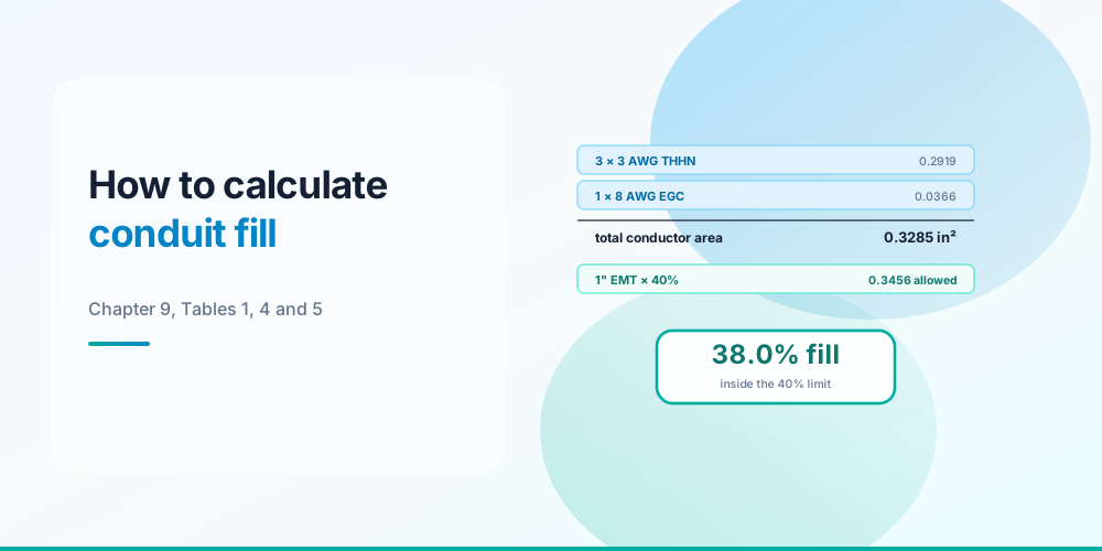
A 100-amp feeder: three 3 AWG THHN (two hots and a neutral) plus one 8 AWG THHN equipment grounding conductor.
Step 1: 3 × 0.0973 = 0.2919, plus 1 × 0.0366 = 0.3285 in²
Step 2 & 3: four conductors, so 40%. Try 3/4” EMT: 0.533 × 0.40 = 0.2132 in² allowed. Our 0.3285 exceeds that - too small.
Try 1” EMT: 0.864 × 0.40 = 0.3456 in² allowed. 0.3285 ≤ 0.3456 ✓
Step 4: 0.3285 ÷ 0.864 = 38.0% fill. Inside the limit with a little room. 1” EMT.
A second one
Six 12 AWG THHN, two 10 AWG THHN, and one 10 AWG equipment ground in 3/4” EMT:
(6 × 0.0133) + (3 × 0.0211) = 0.0798 + 0.0633 = 0.1431 in²
Nine conductors → 40%. 3/4” EMT allows 0.533 × 0.40 = 0.2132 in². Fill is 0.1431 ÷ 0.533 = 26.8% ✓ comfortable.
But - those eight current-carrying conductors trigger a 0.70 bundling factor under 310.15(C)(1). The fill is fine; the ampacity needs checking, and that’s a separate calculation. Conduit Fill Chart shows how often derating binds before fill does.
Why Annex C Sometimes Reads One Higher
If you check your arithmetic against Annex C you’ll occasionally find it one conductor more generous. That isn’t an error in either place - it’s Note 7 to the Chapter 9 tables.
Note 7 - the 0.8 rounding rule
Note 7 permits rounding up to the next whole conductor when the calculation results in a decimal of 0.8 or larger - and only where the conductors are all of the same size. Annex C was built with that rule applied, so:
| Case | Raw calculation | Strict | Annex C |
|---|---|---|---|
| 3/4” EMT, 14 AWG | 21.98 | 21 | 22 |
| 3/4” EMT, 8 AWG | 5.83 | 5 | 6 |
| 1” EMT, 12 AWG | 25.98 | 25 | 26 |
Two things follow. First, for a uniform fill Annex C is authoritative and you can take the higher number - the code explicitly permits it. Second, for a mixed fill Note 7 does not apply at all, because it’s written for conductors all of the same size, so you compute strictly.
Our Conduit Fill Calculator computes strictly throughout, which means at these exact boundaries it will read one conductor lower than Annex C. That’s deliberately conservative rather than wrong - but if you’re at a boundary on a same-size fill and that extra conductor matters, check Annex C.
What Counts, and What Trips People Up
- Every conductor counts toward fill, including the equipment grounding conductor and neutrals. Fill is physical.
- Only current-carrying conductors count for derating. Different rule, different purpose - don’t conflate them.
- Use the right insulation table. XHHW-2 is larger than THHN in small sizes (0.0181 vs 0.0133 at 12 AWG).
- Multiconductor cables are treated by their overall diameter as a single conductor for fill, not by summing the conductors inside.
- Trade size isn’t inside diameter. Always go to Table 4.
- 360 degrees of bend maximum between pull points (358.26 for EMT). A legal fill you can’t physically pull is no use.
Do It Automatically
Conduit Fill Calculator - add any mix of conductors, choose the raceway, and get fill percentage, the applicable limit, and how many more will fit.
The Conduit Fill Calculator reads from the same Chapter 9 tables shown above, and handles the count-dependent limit properly - which matters because you can’t find a maximum count by dividing once when the percentage moves with the answer. Check the ampacity side with the Ampacity Calculator, size the conductors with the Wire Size Calculator, and see Box Fill Calculation for the boxes at either end.
Sources & standards: NEC (NFPA 70) 2023 - Chapter 9 Table 1 and Notes 4 and 7, Table 4, Table 5, Annex C, 310.15(C)(1), 358.26. Table values as published; computed results cross-checked against Annex C. Local amendments override the model code, and the AHJ has final say.
FAQ
How do you calculate conduit fill?
Total the cross-sectional areas of every conductor from Chapter 9 Table 5, find the raceway’s internal area from Table 4, and multiply that area by the Table 1 limit - 53% for one conductor, 31% for two, 40% for three or more. The conductor total must not exceed that figure. Divide conductor area by the raceway’s full area to state it as a percentage.
What is the formula for conduit fill?
Fill % = (total conductor area ÷ raceway internal area) × 100, with the result compared against 53%, 31% or 40% depending on how many conductors there are. Both areas come from Chapter 9 - Table 5 for conductors including insulation, Table 4 for raceways.
Do I use Table 4 or Annex C?
Either, for a fill of identical conductors. Annex C is faster and incorporates the Note 7 rounding allowance, so it’s authoritative for uniform fills. For a mixed fill you must use the Chapter 9 area method, because Note 7 and the Annex C tables only apply where every conductor is the same size.
Why does my conduit fill calculation differ from Annex C?
Note 7 to the Chapter 9 tables allows rounding up when a same-size calculation produces a decimal of 0.8 or larger, and Annex C is built with that applied. A strict area comparison doesn’t round up, so it reads one conductor lower at those exact boundaries - 3/4” EMT with 14 AWG THHN is 21.98, which is 21 strictly and 22 in Annex C.
What is the 60% fill rule?
Note 4 to Chapter 9 Table 1 permits 60% fill in a nipple - a raceway no longer than 24 inches. The same note also exempts a nipple from the 310.15(C)(1) bundling adjustment factors, so short nipples between adjacent enclosures get both allowances.
Does conduit fill include the ground wire?
Yes. Fill counts every conductor physically in the raceway, equipment grounding conductors included. It’s ampacity derating that excludes them - only current-carrying conductors count for 310.15(C)(1).