
Available Fault Current: The Point-to-Point Method and AIC Ratings
- 04 Aug, 2026
Every breaker has two current ratings, and one of them gets ignored. The trip rating is the number on the handle. The interrupting rating - the AIC - is how much fault current the device can safely clear without failing, and it’s printed much smaller.
Install a 10 kA breaker where 15 kA is available and the device may not open the fault. It can rupture instead. 110.9 requires equipment intended to interrupt current at fault levels to have an adequate interrupting rating, and 110.24 requires service equipment to be field-marked with the available fault current.
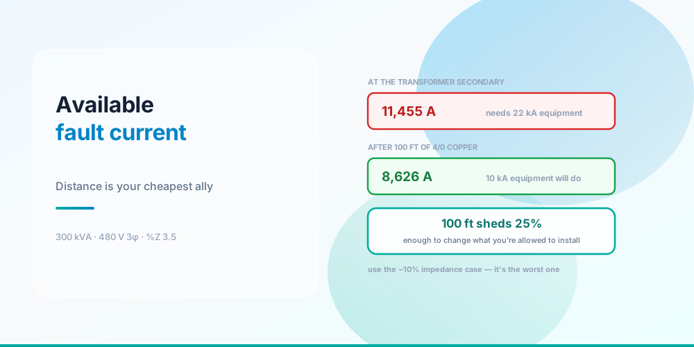
The number that makes this practical: distance sheds fault current fast. A 300 kVA 480 V transformer delivers 11,455 A at its secondary terminals, needing 22 kA equipment. Fifty feet of 4/0 copper later, 10 kA equipment is sufficient.
At the Transformer
300 kVA, 480 V three-phase, 3.5% nameplate impedance
The transformer is almost always the fault-current source that matters, and the calculation is two steps:
FLA = kVA × 1000 ÷ (V × √3)
I_fault = FLA ÷ (%Z ÷ 100)- FLA: 300,000 ÷ (480 × 1.732) = 360.8 A
- Fault current: 360.8 ÷ 0.0315 = 11,455 A
Note the impedance used: 3.15%, not the 3.5% on the nameplate.
| Impedance assumption | Effective %Z | Fault current | Minimum AIC |
|---|---|---|---|
| Nameplate as marked | 3.50% | 10,310 A | 22,000 A |
| NEMA −10% tolerance | 3.15% | 11,455 A | 22,000 A |
NEMA permits ±10% on transformer impedance, and the low side is the worst case - lower impedance means more fault current. Using the nameplate figure understates the available fault current by 11.1%, and on a marginal AIC check that’s exactly the error that gets equipment specified one band too low.
This is counter-intuitive if you think of impedance as a good thing. For voltage regulation, low impedance is better. For fault duty, low impedance is worse. You don’t get to choose which one you want.
Down the Run
Distance sheds fault current fast
| Run length | Available fault current | Minimum AIC |
|---|---|---|
| 0 ft | 11,455 A | 22,000 A |
| 25 ft | 10,587 A | 22,000 A |
| 50 ft | 9,841 A | 10,000 A |
| 100 ft | 8,626 A | 10,000 A |
| 200 ft | 6,917 A | 10,000 A |
| 400 ft | 4,954 A | 10,000 A |
100 feet of 4/0 sheds 25% of the fault current. And because the standard AIC bands are coarse - 10 kA, 22 kA, 25 kA, 42 kA, 65 kA - a modest reduction can move you across a band boundary and change what you’re permitted to install. Here the boundary falls at about 50 feet.
That’s a real design lever. Where a panel is marginal on interrupting rating, moving it further from the transformer is sometimes cheaper than specifying higher-rated equipment throughout - though obviously you’re then buying conductor, and the voltage-drop consequence follows you.
The method
The classic point-to-point method uses an f factor and a multiplier M:
f = (1.732 × L × I_upstream) ÷ (C × n × V)      (three-phase)
M = 1 ÷ (1 + f)
I_downstream = I_upstream × M
The version used here is algebraically the same thing but derived from real impedance instead of proprietary C constants:
- Infer the source impedance from the upstream fault current: Z_source = V_phase ÷ I_upstream.
- Compute the run’s impedance from Chapter 9 Table 8 resistance and Table 9 reactance.
- f = Z_run ÷ Z_source, and M = 1 ÷ (1 + f).
At 100 feet: Z_run = 0.00794 Ω, Z_source = 0.02419 Ω, so f = 0.3280 and M = 0.7530 - the 25% reduction. Using the real tables rather than C values means the same calculation works for any conductor in the tables, and it’s the approach in the Conductor Resistance Calculator.
One detail worth stating: three-phase uses the phase voltage against a one-way conductor impedance, while a single-phase line-to-line fault uses the full voltage and both conductors. Getting that wrong by a factor of two is easy.
What Reduces Fault Current, and What Doesn’t
Reduces it: conductor length, smaller conductors, higher transformer impedance, fewer parallel sets. Also nonmagnetic raceway versus steel, slightly - steel raceway increases reactance.
Increases it: shorter runs, larger conductors, parallel conductors, lower transformer impedance, a larger transformer, multiple sources in parallel.
Doesn’t change it: the breaker’s trip rating, the load, the power factor of the load. Fault current is set by the source and the impedance between it and the fault - not by what’s normally drawing current.
A common surprise: upsizing conductors for voltage drop raises the fault current downstream. The two design goals pull against each other, and on a long feeder to a subpanel it’s worth checking both.
Where the Numbers Are Required
110.24 - service equipment in other than dwelling units must be field-marked with the maximum available fault current, including the date, and the marking must be updated when modifications change it. This is frequently missing on older installations and is a routine inspection item.
110.9 - interrupting rating adequate for the available fault current at the point of application.
110.10 - the circuit impedance, short-circuit current ratings and other characteristics must be selected so the fault is cleared without extensive damage. This is the series-rating and SCCR territory.
409.110 and 440.4(B) - industrial control panels and A/C equipment must be marked with a short-circuit current rating (SCCR), and installing an assembly with a 5 kA SCCR where 11 kA is available is a violation even if every breaker in it is adequately rated. SCCR is an assembly rating, and it’s usually the lowest-rated component that sets it.
Series ratings let a downstream device with a lower individual AIC be used behind a specific upstream device, but only for tested combinations documented by the manufacturer. You cannot reason your way to a series rating; you look it up.
The Limits of This Calculation
A planning tool, and it's worth knowing its edges
Being explicit, because a point-to-point figure gets misused:
What it gives you - symmetrical RMS fault current for one transformer and one run. Enough for an interrupting-rating check and for planning.
Where it’s conservative on purpose - an infinite primary source overstates the fault current, since the utility’s actual impedance is not zero. The −10% impedance assumption is the worst case. No credit is taken for upstream conductor length. All three errors point the safe way.
What it does not model:
- Motor contribution. Running motors act as generators for the first few cycles and add to the fault. On a motor-heavy installation this is a real increment.
- Multiple or parallel sources. Two transformers, or a generator running in parallel, add.
- Asymmetrical peak current. The first half-cycle peak can be substantially higher than the symmetrical RMS value, which matters for mechanical withstand.
- Arc-flash incident energy. Completely different calculation, needs IEEE 1584 and real study software.
Marginal ratings, coordination studies and arc-flash labelling need a licensed engineer. If your calculated fault current is close to an equipment rating, that’s the moment to stop using a planning tool.
Common Mistakes
- Using nameplate impedance instead of the −10% case. Understates fault current by about 11%.
- Confusing trip rating with interrupting rating. The AIC is the small number, and it’s the one that matters here.
- Assuming higher impedance is worse. For fault duty it’s better; for voltage regulation it’s worse.
- Ignoring SCCR on assemblies. A panel’s assembly rating can be far below its breakers’ individual AIC.
- Inventing a series rating. Only tested, manufacturer-documented combinations count.
- Forgetting the 110.24 field marking. Required on non-dwelling service equipment, and must be updated after changes.
- Not re-checking after upsizing conductors. Bigger conductors for voltage drop raise downstream fault current.
- Using single-phase and three-phase formulas interchangeably. Different driving voltage and different loop impedance.
- Treating this as an arc-flash calculation. It isn’t one.
Run the Calculation
Short Circuit Calculator - enter the transformer kVA, secondary voltage, phase and impedance with or without the tolerance margin, then the conductor size, material, raceway type and run length. It returns the fault current at the secondary and at the far end, the f factor and multiplier, and the minimum standard interrupting rating for each point.
Pair it with the Transformer Sizing Calculator and the Conductor Resistance Calculator. See Transformer Sizing for the source, Motor Circuit Sizing for the loads that contribute, and Ohm’s Law Explained for why effective impedance is R·cos θ + X·sin θ rather than the magnitude.
Sources & standards: NEC (NFPA 70) 2023 - 110.9, 110.10, 110.24, 409.110, 440.4(B), and Chapter 9 Tables 8 and 9 for conductor resistance and reactance. The ±10% transformer impedance tolerance is NEMA practice. Arc-flash incident energy is IEEE 1584 and outside the scope of this method. This is a planning calculation; marginal ratings, coordination studies and arc-flash labelling require a licensed engineer.
FAQ
What is available fault current?
The maximum current that would flow if a bolted short circuit occurred at a given point. It’s set by the source and the impedance between the source and the fault - not by the connected load. It matters because every protective device has an interrupting rating, and installing a device where more fault current is available than it can clear risks the device failing violently instead of opening.
How do I calculate fault current at a transformer secondary?
Divide the secondary full-load current by the per-unit impedance. A 300 kVA 480 V three-phase transformer has an FLA of 360.8 A, and at 3.5% impedance that’s 360.8 ÷ 0.035 = 10,310 A. Apply the NEMA −10% impedance tolerance and the effective impedance becomes 3.15%, raising the figure to 11,455 A - which is the number to use for an interrupting-rating check.
Why use the −10% impedance instead of the nameplate value?
Because NEMA allows ±10% on transformer impedance, and lower impedance produces more fault current. The low-impedance case is therefore the worst case for an interrupting-rating check. Using the nameplate value understates the available fault current by about 11%, which is enough to specify equipment one AIC band too low on a marginal installation.
What is an AIC rating?
The ampere interrupting capacity - how much fault current a protective device can safely interrupt. It’s separate from and much larger than the trip rating: a 20 A breaker might have a 10,000 A interrupting rating. NEC 110.9 requires it to be adequate for the fault current available at that point. Standard bands are 10 kA, 22 kA, 25 kA, 42 kA, 65 kA and 100 kA.
How much does fault current drop over a conductor run?
More than people expect. From an 11,455 A source, 4/0 copper in steel raceway gives 10,587 A at 25 ft, 9,841 A at 50 ft and 8,626 A at 100 ft - a 25% reduction over 100 feet. Because AIC bands are coarse, that’s often enough to cross a boundary: in this example the requirement drops from 22 kA to 10 kA equipment at about 50 feet.
What is the point-to-point method?
A hand calculation for fault current at successive points in a system. It computes f = (1.732 × L × I) ÷ (C × n × V) for three-phase, then a multiplier M = 1 ÷ (1 + f), and applies that multiplier to the upstream fault current. It’s algebraically the same as inferring the source impedance from the upstream fault current, adding the run’s own impedance from Chapter 9 Tables 8 and 9, and recomputing - which avoids needing proprietary C constants.
Does this calculation cover arc flash?
No. Arc-flash incident energy is a separate calculation under IEEE 1584 that depends on the fault current, the clearing time of the upstream device, the electrode configuration and the working distance. Available fault current is one input to it. Arc-flash labelling requires an engineered study, not a point-to-point planning figure.
What is SCCR and how is it different?
Short-circuit current rating - an assembly rating marked on industrial control panels under 409.110 and on A/C equipment under 440.4(B). It’s usually set by the lowest-rated component in the assembly, so a panel full of 22 kA breakers can still have a 5 kA SCCR. Installing that assembly where 11 kA is available is a violation even though every individual breaker is adequate.