
The Solar 120% Rule: NEC 705.12 Busbar Math, Done Right
- 05 Aug, 2026
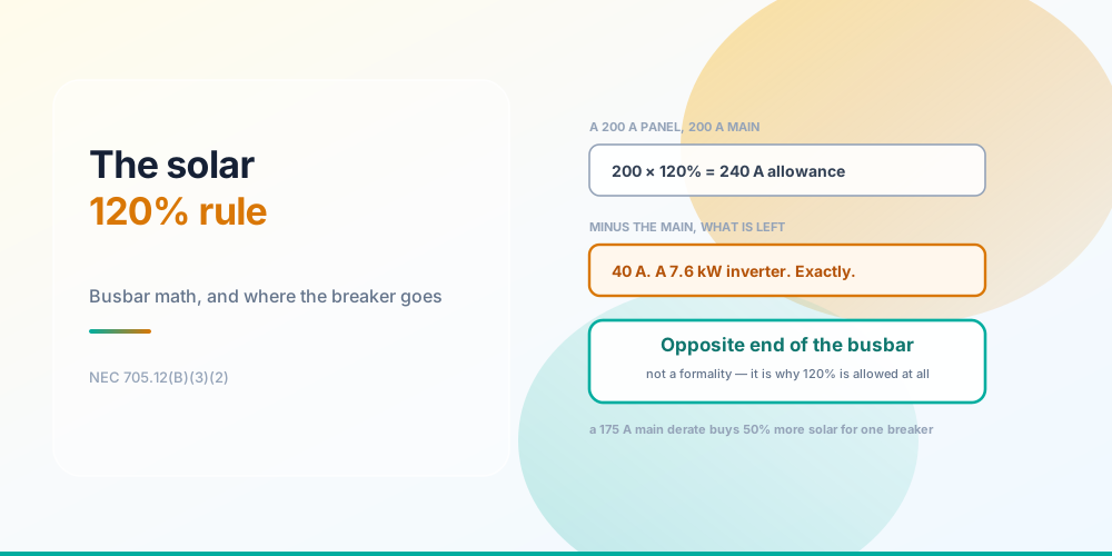
On a standard 200 A panel with a 200 A main, the solar interconnection you are allowed is exactly 40 amps of breaker. That backs a 32 A inverter - about 7.6 kW at 240 V - and it lands precisely on the limit with zero headroom.
Not “about 40”. Forty. Move up one inverter step to 40 A of output and you need a 50 A breaker, the sum becomes 250 A against a 240 A allowance, and it fails. Eight amps of inverter is the whole decision on most residential retrofits.
That is why 7.6 kW is such a suspiciously common inverter size. It is the largest one that drops into a stock 200 A panel with no other work.
Why 120% Is Allowed at All
Opposite ends is the whole justification
Putting 240 A of overcurrent devices on a 200 A busbar sounds like it should be obviously wrong. It isn’t, and the reason is about where the current goes rather than how much of it there is.
With the utility main at one end of the bar and the PV breaker at the other, power enters from both ends and flows inward toward the loads in between. No single section of busbar ever carries the arithmetic sum. The worst-loaded section carries the larger of the two sources, which is still 200 A - exactly what the bar is rated for.
Move that PV breaker up next to the main and the argument collapses. Both sources now feed the same end, all 240 A passes through the top section of bar, and the panel is overloaded by 40 A with nothing to indicate it.
This is why 705.12(B)(3)(2) makes the placement a condition, not a recommendation. In a typical load centre with the main at the top, the PV breaker goes in the very bottom pair of spaces - not near the bottom, the last position. If something already occupies it, that something moves. A permanent warning label is required on the panel so the next person to open it knows why.
The Arithmetic
PV breaker  = inverter continuous output × 1.25 → next standard rating
allowance   = busbar rating × 120%
test        = main breaker + PV breaker ≤ allowance
Two details do most of the damage in practice.
It compares breakers, not kilowatts. The sum uses device ratings. You get to the PV breaker from the inverter’s continuous AC output at 125% under 690.8(A) and 705.28 - a 32 A inverter needs 32 × 1.25 = 40 A. Reaching for the array’s DC nameplate instead is the single most common error.
It is the busbar rating, not the main breaker rating. These are usually the same number and occasionally are not. A 225 A busbar with a 200 A main gives a 270 A allowance and 70 A of room - worth checking the panel label rather than assuming.
The largest inverter each panel will take
| Busbar / main | 120% allowance | Max PV breaker | Max inverter | ≈ kW at 240 V |
|---|---|---|---|---|
| 100 A | 120 A | 20 A | 16.0 A | 3.84 kW |
| 125 A | 150 A | 25 A | 20.0 A | 4.80 kW |
| 150 A | 180 A | 30 A | 24.0 A | 5.76 kW |
| 200 A | 240 A | 40 A | 32.0 A | 7.68 kW |
| 225 A | 270 A | 45 A | 36.0 A | 8.64 kW |
| 400 A | 480 A | 80 A | 64.0 A | 15.36 kW |
There is a tidy pattern hiding in that table. When the main equals the busbar, the allowance leaves exactly 20% of the busbar rating for the PV breaker, and dividing by 1.25 means the usable inverter is always 16% of the panel rating. A 200 A panel takes 32 A; a 400 A panel takes 64 A.
When It Fails - Three Ways Out
A main breaker derate is the cheap fix
1. Derate the main breaker - usually cheapest
Dropping a 200 A main to 175 A on a 200 A busbar leaves 65 A of allowance, which rounds down to a 60 A PV breaker and a 48 A inverter - about 11.5 kW. Fifty percent more solar for the price of one breaker.
The obvious question is whether the house can live on 175 A, and for the overwhelming majority of homes the answer is yes with room to spare. NEC 220.87 is how you prove it: twelve months of the utility’s recorded peak demand, multiplied by 125%, establishes the existing load. A typical single-family house peaks somewhere in the 40–60 A range. The method is worked through in NEC 220.87: Using Utility Data.
Derating further keeps opening room - 150 A allows a 90 A breaker, 125 A allows 110 A - but at some point you are constraining the house to feed the array, and that trade needs to be deliberate.
2. Supply-side tap under 705.11
Connecting ahead of the service disconnect puts the PV outside the busbar rule entirely, because there is no busbar involved. 705.11 governs it, the tap conductors have their own sizing rules, and it usually means work in or beside the meter enclosure - which means utility coordination and often a meter pull.
More expensive and more disruptive than a breaker swap, but it is the reliable answer when the array is genuinely too large for the panel.
3. Fit a smaller inverter
Unglamorous, and sometimes correct. Inverter clipping is not the disaster it sounds like: a system slightly undersized on the AC side loses only the top of a handful of peak hours a year, and DC-to-AC ratios above 1.2 are routine in good design.
And one more the code added
705.13 power control systems are increasingly the answer on panels that will not otherwise take an interconnection. A listed PCS actively limits current onto the busbar, so the busbar sees a controlled figure rather than a breaker rating. Several battery-and-inverter products are listed for this, and where one is available it can solve a busbar problem with no panel work at all.
The Other Options in 705.12(B)(3)
The 120% rule is one path, not the only one, and treating it as the only one gets interconnections refused unnecessarily. 705.12(B)(3) also contains:
- The sum rule. Where the sum of all breakers supplying power, excluding the main, does not exceed the busbar rating. Useful on panels with a small main.
- The centre-fed allowance. For panelboards fed at the centre of the bar, with its own conditions.
- Engineering supervision. A licensed engineer may perform a load study and document a connection that none of the prescriptive options permit.
If the 120% check fails, read the section before quoting a service upgrade.
Batteries Count Too
NEC 2020 rewrote Article 705 around all power production sources, not just PV. An energy storage system interconnected on the load side faces the same busbar arithmetic, because a battery inverter that can export is a source like any other.
Two wrinkles worth flagging. A system that both charges and discharges may need consideration in both directions depending on the equipment and the AHJ. And where a battery is paired with PV behind one inverter, what matters is the inverter’s rated output, not the sum of the two nameplates.
Common Mistakes
- Using the array’s DC kW instead of the inverter’s AC output. The rule is about the breaker, sized from continuous AC current at 125%.
- Forgetting the 125% factor. A 32 A inverter is a 40 A breaker, not a 35 A one.
- Putting the PV breaker anywhere but the far end. That placement is the justification for the allowance.
- Using the main breaker rating instead of the busbar rating. Usually the same; check the label when they aren’t.
- Skipping the warning label. It is required, and inspectors look for it.
- Assuming 120% is the only option. 705.12(B)(3) has several paths, and 705.13 adds another.
- Quoting a service upgrade before trying a main derate. A $60 breaker frequently solves it.
- Rounding the PV breaker up to “make it work”. The breaker follows the inverter; it is not a free variable.
- Treating batteries as exempt. Article 705 covers all power production sources.
Check Your Panel
Solar 120% Rule Calculator - enter the busbar rating, the main breaker and the inverter’s continuous output, and it sizes the PV breaker at 125%, applies the 120% test, and tells you the largest inverter that panel will accept. It also shows the arithmetic line by line, so you can hand it to an inspector or a homeowner.
Size the string with the Solar String Sizing Calculator, and if you are considering a main derate, prove it first with the Existing Load Calculator. Check there is a free space at the far end of the bar with the Panel Spaces & Tandem Breaker Calculator.
Sources & standards: NEC (NFPA 70) 2023 - Article 705, including 705.11 (supply-side source connections), 705.12 (load-side source connections) with the busbar options at 705.12(B)(3) and the 120% allowance at 705.12(B)(3)(2), 705.13 (power control systems) and 705.28 (circuit sizing and current); Article 690 for PV specifically, including 690.8(A) circuit current. The opposite-end busbar placement and the permanent warning label are conditions of the 120% allowance, not recommendations. NEC 2020 restructured Article 705 to cover all power production sources including energy storage. Utility interconnection agreements impose their own requirements independent of the NEC. Local amendments override the model code and the AHJ has final say.
FAQ
What is the solar 120% rule?
NEC 705.12(B)(3)(2) permits the main overcurrent device and the backfed PV breaker together to total up to 120% of the panel’s busbar rating, provided the PV breaker is located at the opposite end of the busbar from the main supply. A 200 A busbar allows 240 A of devices, so a 200 A main leaves exactly 40 A for solar - a 32 A inverter, roughly 7.6 kW at 240 V.
Why is 120% allowed when the busbar is only rated for 100%?
Because current enters from both ends. With the main at one end and the PV at the other, power flows inward toward the loads between them, so no section of busbar carries the sum of the two devices - the worst section carries the larger source alone, which is within the bar’s rating. That is the entire engineering basis, and it is why the opposite-end placement is a condition rather than a suggestion.
How big a solar system can a 200 amp panel take?
With a 200 A main, 32 A of continuous inverter output - about 7.6 kW at 240 V. The arithmetic is 200 × 120% = 240 A allowance, minus the 200 A main leaves 40 A of PV breaker, and 40 ÷ 1.25 = 32 A of inverter. Derating the main to 175 A raises it to a 60 A breaker and a 48 A inverter, around 11.5 kW.
What if my panel fails the 120% rule?
Three main routes. Derate the main breaker - dropping 200 A to 175 A opens up 50% more solar for the cost of one breaker, and NEC 220.87 measured demand is how you show the house never needs 175 A. Use a supply-side tap under 705.11, which connects ahead of the service disconnect and bypasses the busbar rule. Or fit a smaller inverter. A listed power control system under 705.13 is a fourth option that is becoming common.
Do I use the inverter’s output or the breaker rating in the 120% calculation?
The breaker rating - but you derive it from the inverter. NEC 690.8(A) and 705.28 require the PV circuit to be sized at 125% of the inverter’s continuous AC output current, so a 32 A inverter needs a 40 A breaker, and that 40 A is what goes into the sum. Using the array’s DC nameplate kilowatts is the commonest way this calculation goes wrong.
Where exactly does the PV breaker have to be installed?
At the opposite end of the busbar from the input feeder or main breaker. In a typical residential load centre with the main at the top, that is the very bottom pair of spaces - the last position, not simply somewhere low. If a breaker already occupies it, relocate that breaker. Inspectors check this specifically, and a permanent label is required on the panel stating the arrangement.
Does the 120% rule apply to battery storage?
Yes. NEC 2020 rewrote Article 705 to cover all power production sources, and an energy storage system interconnected on the load side faces the same busbar arithmetic - a battery inverter capable of export is a source. Where a battery and PV share a single inverter, the inverter’s rated output is what counts rather than the sum of the two nameplates.
Is a supply-side tap better than the 120% rule?
Not better, just different. A supply-side connection under 705.11 lands ahead of the service disconnect, so there is no busbar to overload and no size limit from this rule at all - which makes it the answer for arrays too large for the panel. The trade-off is cost and disruption: it usually means work in or beside the meter enclosure, utility coordination, and often a meter pull. Try a main derate first.